


ITRT-PGY Test Power Supply Panel
Technical Manual
1、Introduction
The ITRT-PGY Test Power Supply Panel may provide on-site relay protection test with a reliable, steady and convenient AC/DC test power supply. In addition, it provides a reliable guarantee for improving the quality of relay protection test and ensuring the safety of the personnel and equipment.
1.1 Purpose
The equipment is suitable for use in power plants, transformer stations and medium-to-large sized industrial enterprises as a standard relay protection test power supply.
1.2 Features
1.2.1 The equipment adopts dual power supply, which can be switched manually or automatically. Through the use of the contactor, the dual power supply can be switched on load to ensure the reliability of power supply.
1.2.2 The AC power supply separates the system power supply from the test power supply with a large-capacity isolation transformer, and a shielding layer is installed between the primary side and the secondary side to prevent the test power supply from being disturbed by the transient process of the grid and other harmonics. The transformer adopts the △/Y0 wiring method to significantly reduce the third harmonic, thus ensuring the quality of power supply.
1.2.3 The AC power supply may regulate the voltage in a continuous and smooth manner to address the needs of different test items.
1.2.4 The AC power supply is controlled using a famous branded switch, which is able to act rapidly and has the tripping function upon short-circuiting and overload with a long service life.
1.2.5 The output AC power supply is provided with a leakage protection switch to ensure the safety of the test personnel. The switch offers such advantages as steady performance, high sensitivity and reliable actions and has the tripping function upon short-circuiting and overload.
1.2.6 The DC circuit breaker of the DC circuit is characterized by rapid actions and long service life with the tripping function upon short-circuiting and overload.
2、Structure
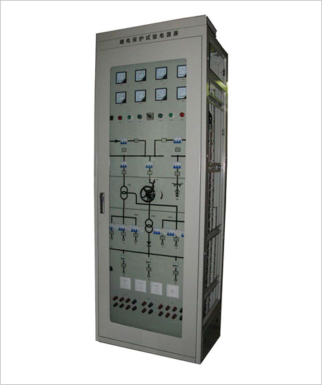
2.1The ITRT-PGY test power supply adopts the PK-10 fully-enclosed cabinet structure with locked front and back doors.
2.2 The main components include the isolation transformer, 3-phase self-coupling voltage regulator, reactor, rectifier, capacitor, automatic air switch, leakage protection switch, ammeter and voltmeter, etc.
2.3 An artificial circuit is available on the panel surface to facilitate identification by the operators so as to avoid mal-operation.
2.4 The instruments, indicators and control switch are located on the front panel, and the input and output lead wires may be connected by means of terminal or terminal block.
3、Operating Conditions
3.1Measures shall be taken to keep off rain and snow in the place(s) where the equipment is operated.
3.2Altitude: Not more than 2000m.
3.3Ambient air temperature: -5℃~+40℃.
3.4The RH shall not exceed 50% at 40℃ or 90% at 20℃.
3.5The mechanical vibration amplitude shall not exceed 0.05mm and the frequency 600/m in the place(s) where the equipment is operated.
3.6The installation inclination in relative to plumb-line shall be not more than 5º.
3.7The surrounding media pose no risk of explosion and there are no conducting dust and corrosive gases.
4、Operating Principles
4.1Electrical Principles (see the Electrical Schematic Diagram)
4.2 Introduction to the Circuit
4.2.1The equipment adopts AC 230V/400V dual power supplies, which are not put into operation simultaneously and may be switched by the contactor. The selection switch “SA” is set to the Manual, Stop and Auto position and may manually switch, stop or automatically switch the power supply. The voltages UAN, UBN and UCN are monitored by the voltmeters 1PV, 2PV and 3PV; the currents IAN, IBN and ICN are monitored by the ammeters 1PA, 2PA and 3PA.
4.2.2The AC circuit receives the output AC voltage AC 230V/400V and AC 57.7V/100V via the isolation transformer “1TM”. AC 230V/400V voltage is controlled and output by the switches 7QF, 8QF, 9QF and 10QF; the AC 57.7V/100V voltage is controlled and output by the switches 11QF and 12QF.
4.2.3 The DC circuit receives the 0~250V continuous adjustable DC voltage from the 3-phase self-coupling voltage regulator 1TC, rectifier transformer 2TM and 3-phase bridge type rectifier circuit and filter circuit, and is monitored by the DC ammeter 4PA and voltmeter 4PV. The rectifier modules 1DC and 2DC generate DC220V and DC110V power supplies respectively.
4.2.4 To allow for convenient wiring upon use, output is available in 3 forms: Terminals on the front side of the panel, terminal block on the back side of the panel and power sockets. (See the Panel Layout and the Terminal Block Diagram).
AC output is available in 3 forms:
“I” and “II” are 230V/400V AC output in the form of terminals on the front side of the panel; “III” and “IV” are 57.7V/100V AC output in the form of terminals on the front side of the panel; “1D” is output in the form of terminal block on the back side of the panel; “PS” is output in the form of power socket.
DC output is available in 3 forms:
“V” and “VI” are DC220V fixed output in the form of terminals on the front side of the panel; “VII” and “VIII” are DC 0~250V adjustable output in the form of terminals on the front side of the panel; “IX” and “X” are DC 110V fixed output in the form of terminals on the front side of the panel;
“1D” is output in the form of terminal block on the back side of the panel.
“PS” is output in the form of power socket.
5、Main Technical Indicators
5.1 AC
5.1.1 Rated input voltage: 3-phase 4-wire 230V/400V; frequency: 50Hz.
5.1.2
Rated output voltage: 230V/400V, 3-phase 4-wire;
Rated output voltage: 57.7V/100V, 3-phase 4-wire.
5.1.3 When 3-phase input is balanced, the output imbalance is less than 1%.
5.1.4 The third harmonic component is less than 3%.
5.1.5The input transformer capacity is 15kVA.
5.2 DC
5.2.1 The power input is AC 3-phase 4-wire AC 230V/400V.
5.2.2 The output DC voltage is 0~250V continuous adjustable voltage, and output in the form of terminals on the front side of the panel, terminal on the back side of the panel and power socket.
5.2.3 The rectifier transformer has a capacity of 5kVA. Under the eight-hour working day system, the maximum output current is 20A.
5.2.4 The output DC ripple coefficient is less than 1.5%.
6、Considerations
When DC output is not in use, turn the voltage regulator counterclockwise to the minimum output so as to turn off the rectifier module.
When the equipment is not in use, all switches shall be set to the OFF position.
Baoding Integrity Electric CO., LTD
ADDRESS: Building 3, University Technology Park, No. 5699, North 2nd Ring, Baoding, Hebei Province, P. R. China
TEL: 0312-3917280/3917283
FAX: 0312-3917281
EMAIL: itrtdq@163.com

